
Design & Engineering
Design and Engineering
Our engineering services cover hydraulic and structural calculations, material selection, detailed fabrication drawings, welding requirements, protective-coating specifications, installation planning and preparation of operation and maintenance documentation.
Equipment can be designed and supplied in accordance with applicable international standards, including ISO, EN, DIN, AWS and ASME, together with the employer’s technical specifications.
All equipment is delivered according to approved project specifications, quality plans and inspection procedures. Quality-control activities may include material traceability, welding qualification, dimensional inspection, non-destructive testing, trial assembly, coating inspection and factory acceptance testing.
Installation
metrading provides installation supervision, mechanical erection, embedded-part alignment, field welding, hydraulic and electrical integration, dry and wet testing, load testing, commissioning and operator training.
From individual equipment packages to integrated hydromechanical systems, Gulf Supply Solution provides complete installation and commissioning support.
Engineering and Design Capabilities
Gulf Supply Solution provides coordinated engineering and design services for hydromechanical equipment, hydraulic steel structures and associated operating systems. Our engineering activities cover the development of project-specific solutions from the initial design criteria through detailed engineering, fabrication documentation and installation support.
The design process considers hydraulic conditions, structural loads, equipment-operating requirements, civil interfaces, expected service life, maintainability and applicable project standards.
Design Basis and Engineering Criteria
At the beginning of each project, the engineering team reviews the employer’s requirements, technical specifications, hydraulic data, civil drawings and operating philosophy.
A project-specific design basis may define:
- Design and maximum water levels
- Operating, emergency and maintenance conditions
- Static and dynamic hydraulic pressures
- Maximum design head
- Flow velocity and discharge requirements
- Hydrostatic, hydrodynamic and uplift forces
- Wave, debris and sediment loads
- Seismic and environmental loads
- Equipment operating frequency
- Allowable deflection and stress limits
- Corrosion allowance
- Design life and fatigue requirements
- Material grades and coating systems
- Applicable codes and standards
- Inspection, testing and acceptance criteria
Engineering Calculation Sheets
Detailed calculation sheets can be generated for each major component and submitted to the employer or engineering consultant for review and approval.
Calculations may include:
- Hydrostatic pressure and resultant water-force calculations
- Hydrodynamic and unbalanced pressure analysis
- Gate skin-plate design
- Horizontal and vertical stiffener calculations
- Main girder and cross-girder design
- Gate-frame and guide-system calculations
- Radial-gate arm and trunnion analysis
- Wheel-load and track calculations
- Seal compression and leakage considerations
- Embedded-part and anchorage design
- Lifting-force and operating-capacity calculations
- Hoist, wire-rope, drum and gearbox selection
- Hydraulic-cylinder sizing
- Lifting-beam and dogging-device calculations
- Stoplog and bulkhead-gate calculations
- Trash-rack structural and hydraulic-loss calculations
- Penstock wall-thickness calculations
- Buckling and external-pressure verification
- Support, saddle and anchor-force calculations
- Branch connection and reinforcement analysis
- Weld sizing and connection design
- Fatigue and serviceability verification
- Transportation and lifting-condition checks
Calculation reports can include the design assumptions, load combinations, material properties, analytical methods, software outputs, utilization ratios and engineering conclusions.
Hydraulic Assessment
Where required, hydraulic considerations are incorporated into the design to confirm that the equipment performs safely under the specified flow conditions.
The assessment may cover:
- Flow velocity through gates and trash racks
- Head loss across intake equipment
- Gate discharge characteristics
- Down pull and uplift forces
- Vibration and flow-induced loading
- Cavitation risk
- Aeration requirements
- Seal arrangement and allowable leakage
- Intake and outlet flow conditions
- Effects of debris and sediment
- Emergency closure requirements
Structural Analysis and Finite Element Modelling
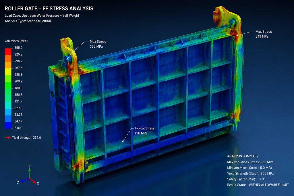
Three-dimensional structural models and finite element analysis can be developed for critical or geometrically complex equipment.
The analysis may be used to evaluate:
- Stress distribution
- Local stress concentration
- Overall and local deformation
- Plate buckling
- Girder stability
- Trunnion and support reactions
- Wheel and guide loads
- Embedded-part behavior
- Lifting and transportation conditions
- Critical welded connections
- Fatigue-sensitive areas
- Seismic response where applicable
The results support design optimization, verification of structural integrity and reduction of unnecessary equipment weight while maintaining the required safety factors.
3D Modelling and Design Coordination
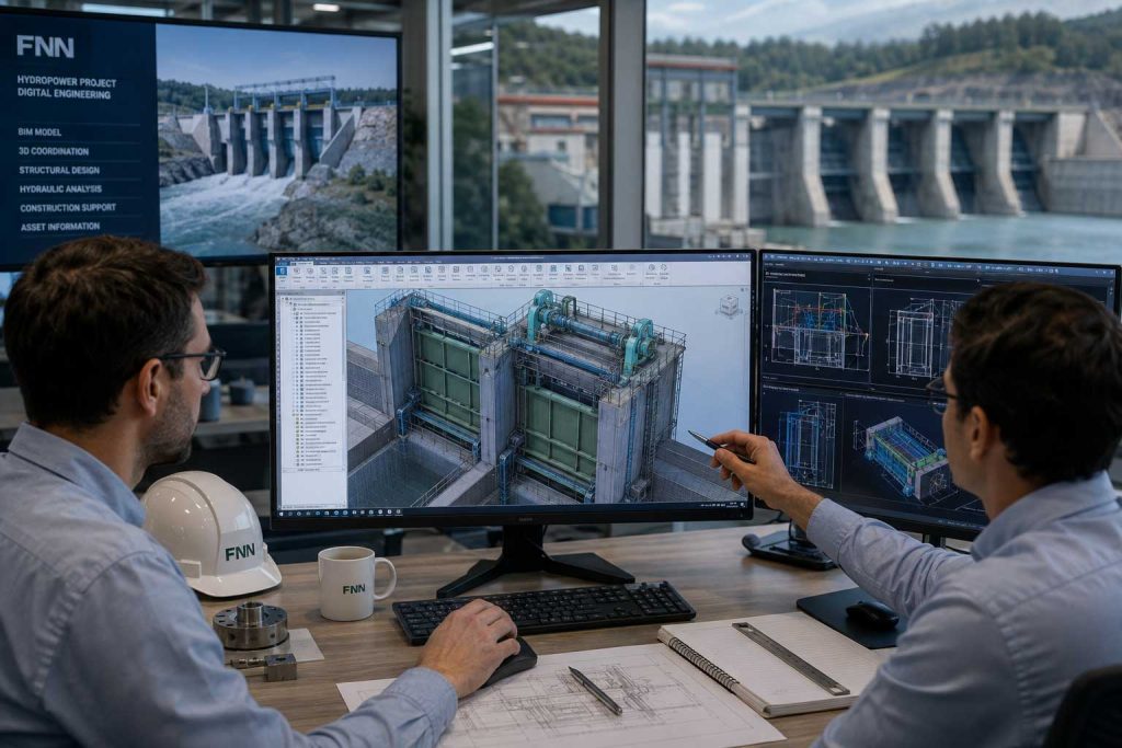
Detailed three-dimensional models can be generated to coordinate the hydromechanical equipment with civil, mechanical, electrical and hydraulic interfaces.
The 3D modelling process supports:
- Equipment configuration and spatial coordination
- Verification of clearances and operating envelopes
- Clash detection
- Coordination with concrete recesses and block-outs
- Embedded-part positioning
- Hoist and crane arrangement
- Access-platform and maintenance-space verification
- Hydraulic-cylinder and piping layout
- Electrical and instrumentation interfaces
- Assembly-sequence planning
- Installation and removal studies
- Weight and center-of-gravity determination
- Preparation of presentation views and exploded assemblies
Where required, the models can be integrated into the project’s BIM coordination process.
General Arrangement and Interface Drawings
General arrangement drawings establish the overall equipment configuration and its interfaces with the surrounding civil works and auxiliary systems.
These drawings may show:
- Main dimensions and equipment levels
- Gate, stoplog and trash-rack arrangements
- Embedded parts and concrete interfaces
- Hoist and operating-system locations
- Access and maintenance requirements
- Installation and removal clearances
- Mechanical and electrical interfaces
- Hydraulic piping routes
- Equipment weights and design loads
- Lifting points and handling arrangements
Interface drawings and load data are issued to the civil designer to support the design of concrete structures, foundations, anchorages and equipment-support areas.
Detailed Fabrication Drawings
Following approval of the general design, detailed fabrication drawings are prepared for manufacturing and inspection.
The fabrication package may include:
- Assembly drawings
- Component and part drawings
- Plate-development drawings
- Machining drawings
- Welding details
- Weld maps
- Material specifications
- Bills of materials
- Bolt and fastener schedules
- Seal and wear-strip details
- Dimensional and geometric tolerances
- Surface-preparation and coating requirements
- Trial-assembly instructions
Drawings are developed to provide clear information for procurement, cutting, forming, welding, machining, assembly, inspection and final installation.
Mechanical and Operating-System Design
The engineering scope may also cover the design and selection of gate-operating and lifting systems.
This includes:
- Required opening and closing forces
- Normal and emergency operating conditions
- Hoist capacity and operating speed
- Hydraulic-cylinder bore and stroke
- Wire-rope and sheave arrangements
- Rope-drum and gearbox selection
- Brake and motor requirements
- Synchronization of multiple lifting points
- Manual and emergency operation
- Mechanical locking and dogging systems
- Gantry-crane and lifting-beam interfaces
- Limit switches and position monitoring
- Safety factors and overload protection
Hydraulic Power Unit Design
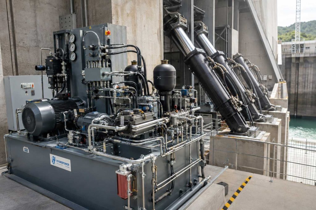
For hydraulically operated gates, the engineering scope may include:
- Hydraulic schematic development
- Cylinder sizing and selection
- Pump and motor capacity
- Oil-reservoir sizing
- Operating-pressure determination
- Valve and manifold selection
- Filtration and cooling requirements
- Accumulator requirements
- Hydraulic piping layout
- Pressure and position instrumentation
- Emergency and manual operation
Electrical, Instrumentation and Control Design
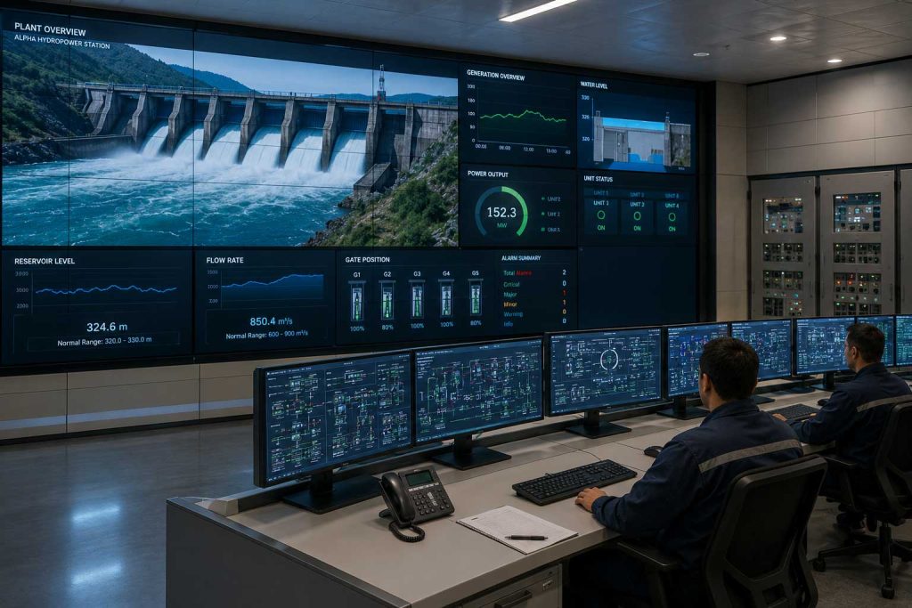
Electrical and control systems can be developed according to the project’s operating philosophy and automation requirements.
The design may include:
- Control philosophy
- Functional design specifications
- Single-line diagrams
- Control-panel layouts
- Motor-control circuits
- PLC architecture
- Input and output lists
- Instrument schedules
- Cable schedules
- Cause-and-effect matrices
- Interlock and alarm logic
- Local and remote-control arrangements
- Gate-position and water-level monitoring
- Emergency shutdown functions
- Communication with the plant control system or SCADA
Design Review and Approval Documentation
Engineering submissions can be organized according to the employer’s document-control and approval procedures.
Typical design deliverables include:
- Design basis report
- Design criteria
- Engineering calculation reports
- Hydraulic assessment
- Structural-analysis reports
- Finite element analysis reports
- General arrangement drawings
- Civil-interface and loading drawings
- Detailed fabrication drawings
- Bills of materials
- Technical data sheets
- Welding and inspection documentation
- Coating specifications
- Installation method statements
- Testing and commissioning procedures
- Operation and maintenance manuals
Comments received from the employer, consultant or third-party reviewer are recorded and incorporated through a controlled document-revision process.
Design for Fabrication, Installation and Maintenance
Hydromechanical equipment is designed not only for structural performance, but also for efficient fabrication, transportation, installation, operation and long-term maintenance.
The engineering team considers:
- Availability of materials and standard components
- Practical welding and machining requirements
- Workshop assembly limitations
- Transportation dimensions and weights
- Site access and crane capacity
- Installation sequence
- Field-joint locations
- Replaceability of seals, wheels and bearings
- Inspection and maintenance access
- Safe lifting and handling points
- Availability of spare parts
- Future rehabilitation requirements
This integrated approach helps reduce project risk, improve constructability and support reliable operation throughout the equipment’s service life.
Applicable Standards
Design and engineering activities can be performed in accordance with the project specifications and applicable international standards, including relevant ISO, EN, DIN, AWS, ASME, IEC and other employer-approved requirements.
All final standards, design criteria, software methods and acceptance requirements are established according to the specific contract and approved project documentation.